Having problems with communicating regarding phone-bt module

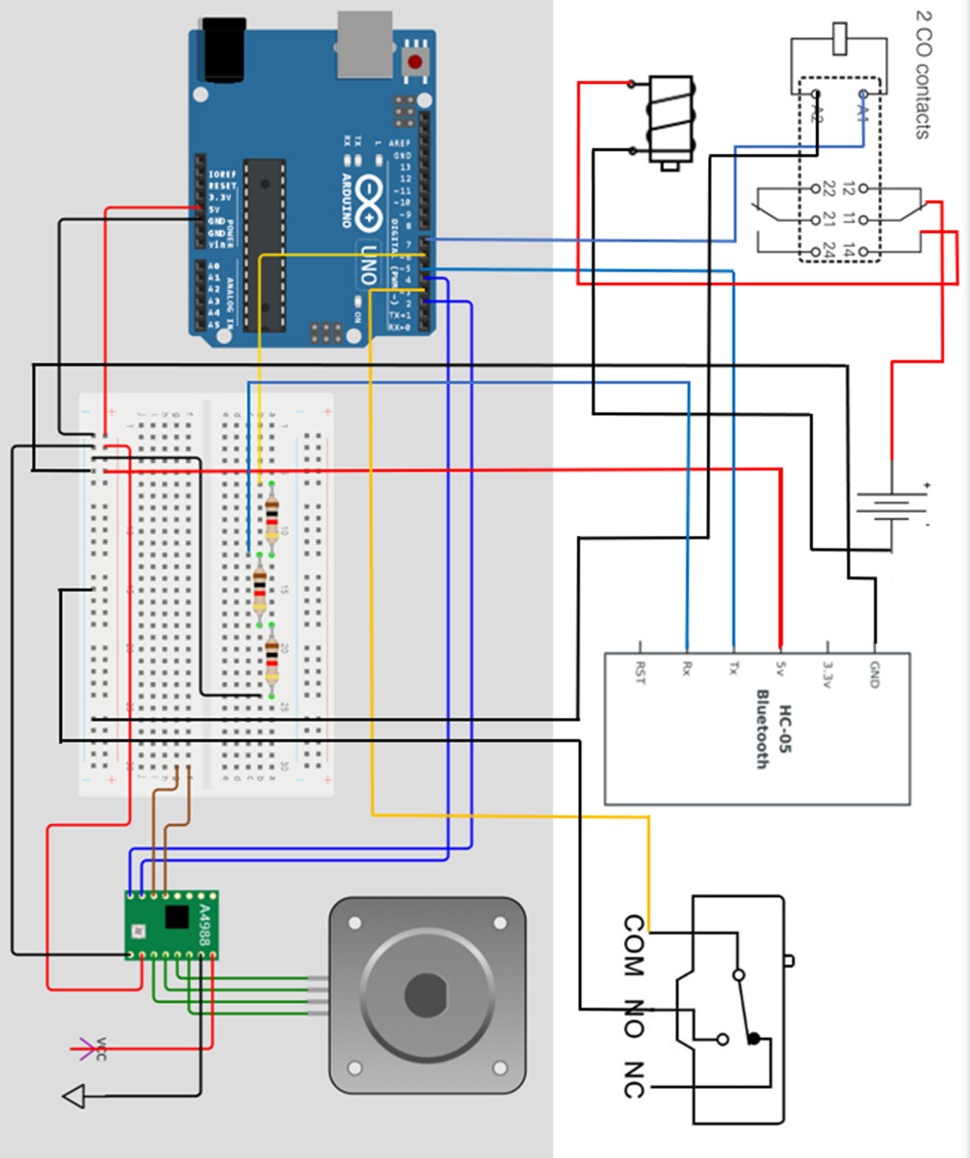
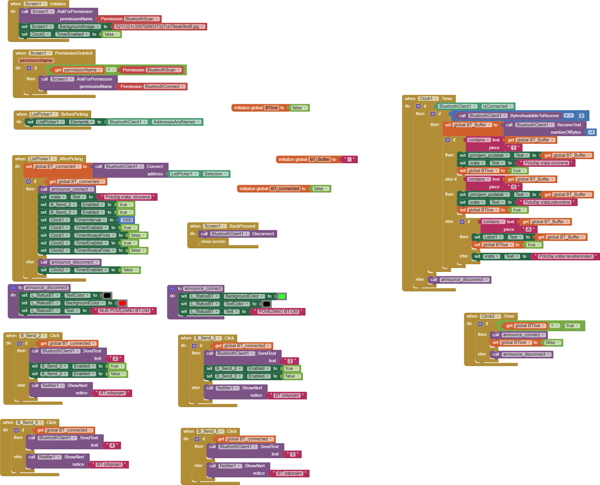
So, with the help of @uskiara I built an app mit app that controls my dog's door, controlls NEMA 17 stepper motor and electromagnet via bt module hc-05. Also with the help of microswitch I change the state of the door(closed/open) based on the digital state.

All of it worked fine until few days ago when I lost the microswitch effect, it just didn't want to change state(I am using internal pull up resistor and I realized my voltage between C pin and NO of the microswitch was 0,4V, whereas when I connect only arduino to the microswitch I had 5V.

Also, my app freeze after I push a button and also, I receive some gibberish data on the serial monitor since yesterday.

Below are my cc code, mit app blocks and schematic I made. I will post serial monitor now.


#include <SoftwareSerial.h>
#define TxPin 6                        
#define RxPin 5                        
#define el_magnet 7
#define command 3
#define debug                           
bool el_magON= false;
unsigned long prethodno_vrijeme=0;
const long interval=15000;
SoftwareSerial BTSerial(RxPin,TxPin);   

char state = ' ';                       
const int stepPin = 4; 
const int directionPin = 2;

int buttonState = LOW;
int lastButtonState = LOW; 
unsigned long lastDebounceTime = 0; 
unsigned long debounceDelay = 50; 
//-----------------------------------------------------------------------------------------------
void zatvori()
{
  digitalWrite(directionPin,LOW);  
  StepperActuate();
}     

//-----------------------------------------------------------------------------------------------
void otvori()
{
  digitalWrite(directionPin,HIGH);  
  StepperActuate();
} 

//-----------------------------------------------------------------------------------------------
void StepperActuate()
{
  for(int x = 0; x < 50; x++) 
     {
        digitalWrite(stepPin,HIGH); 
        delayMicroseconds(500);  
        digitalWrite(stepPin,LOW); 
        delayMicroseconds(500);  
     }
}
//===============================================================================================
void setup() 
{
  pinMode(el_magnet,OUTPUT);
  digitalWrite(el_magnet,LOW);
  pinMode(command,INPUT_PULLUP);
  pinMode(stepPin,OUTPUT);
  pinMode(directionPin,OUTPUT);
 
  BTSerial.begin(9600);               
  Serial.begin(9600);                 
}

//===============================================================================================
void loop() 
{   
   int reading = digitalRead(command);

  
  if (reading != lastButtonState) {
    lastDebounceTime = millis();
  }

  
  if ((millis() - lastDebounceTime) > debounceDelay) {
    
    if (reading != buttonState) {
      buttonState = reading;
      
      
      if (buttonState == HIGH) {
        BTSerial.println("1");
      } else {
        BTSerial.println("0");
      }
    }
  }
  lastButtonState = reading;

 static char character = 'A'; 
  static unsigned long lastPrintTime = 0; 
  unsigned long currentTime = millis(); 
  if (currentTime - lastPrintTime >= 90000) { 
    BTSerial.println(character); 
    lastPrintTime = currentTime; 
  }

if (BTSerial.available())                     
   {
    state = BTSerial.read();                  
#ifdef debug
    Serial.print("Received : ");              
    Serial.println(state);
#endif    
    if(state=='2')                                      
      {
        otvori();
      }
          
    if(state=='3')                                                   
      {
        zatvori();
      }
              
    if(state=='4') {
   digitalWrite(el_magnet,LOW); 
  el_magON=false; 
 }      
      
if(state=='5') {
if (!el_magON) {
  digitalWrite(el_magnet, HIGH);
  el_magON=true;
  prethodno_vrijeme=millis();
}
}
}

unsigned long trenutno_vrijeme=millis();
if (el_magON && (trenutno_vrijeme-prethodno_vrijeme>=interval)){
  digitalWrite(el_magnet, LOW);
  el_magON=false;
}
}

I know there is a lot going on here but I really have no idea why these weird behaviour happens.

UPDATE: here I tried to connect only bt module, so vcc, gnd, tx and rx pins to arduino only. I received nothing until I disconnected the bt module and below you can see what happened.

1 Like

Dear @Bruno_Dragas,
the message you got from the HC05 is sent by the shield when it is still working in AT mode.

This probably explains why you're getting rubbish from it. In AT mode it works @38400 baud while in your Arduino code you're setting it @9600.

Moreover, if the HC05 blinks twice every 2 seconds, this is a confirmation that the HC05 is set in AT mode.
Please check the annexed link and verify to exit from AT mode (i.e. when you cease to transmit, the "disk success" message shall not appear, when the HC05 is working in normal mode).

Ciao, Ugo.

Dear Ugo, my module blinks fast when powered, and I grounded the pin 34 which should unable the possibility of entering AT mode, because I found an info where they say you need to put the pin34 HIGH to enter AT mode. Now, I don't know...

Dear @Bruno
I agree with you that the information that we (you and I) got seem to be opposite :flushed: but the message you shown seems really to be a signal that the HC05 is in AT mode.
@Juan_Antonio, @ChrisWard what are your thought about ?
Cheers, Ugo.

A little update, I tried bt module with my arduino without motor, driver, etc... only using voltage divider on my soldered board for the rx pin of the module. Communication is good, without gibberish data received, but what caught my eye is the relay that keeps getting activated/deactivated when I power on or power off the arduino🙃 even though I declared the pin 7 state as low at the beginning
!!! Using Serial bt terminal I realized I don't receive char 'A' which I use as a handshake method...

Also, as a basic test, I tried to send hello world to serial monitor and for some reason rx pin blinks instead of tx?

Well, if Bruno is human, then like me, he can get some of the circuit wrong but be convinced that it is right.

Bruno, we have your diagram, can you take a photo of the actual set-up?

Well, I believe you won't get anything out of it, it is really hard to follow by photo. Still, I will take a photo when I get home

:grin: :grin: :grin:
Dear Chris, nice to read you again !
... in effect our electronics professor at the university was used to say that:
"electronics is the demonstration of the existence of the "Saint Spirit"....

Hi Bruno

I think there is every chance of there being an issue that is difficult to spot with the human eye, I have been there and done that.

I suggest you build again, but this time start with the Arduino and HC-05 alone, communicating simple data with a simple App to establish a Bluetooth connection that is reliable for a good period of time -at least 1 hour without any glitches whatsoever. You can then move on to build on that good foundation.

Ensure the hardware is properly powered using an AC to DC adaptor (7v to 12v max DC output). The adaptor will need to supply up to an amp later on when your hardware has the stepper motor added. Also ensure that:

  1. There is nothing near that can interfere with Bluetooth.
  2. There is nothing getting too hot.

Bluetooth checklist:
https://www.professorcad.co.uk/appinventortips#BluetoothFailure

1 Like

Hi, I am vers positive now that everything works fine, I checked it with my professor and I tried to re-solder it and now it works fine. Again, I burned myself before by saying it works so...

2 Likes

Dear @Bruno_Dragas,
is this the right one ? :rofl: :rofl: :rofl:

So it was a HW problem ? A bad contact or whatever ?
Cheers.

Well, correct, it was something with the soldering that didn't quite work out

Thanks Bruno for having shared you final result !
Then, best wishes for you (next) project :hugs: :hugs: :hugs:
Ugo.

Thank you for being patient with me throughout this journey... I hope this is it, I had a problem with microswitch again, with contact again but I solved it and it all works fine now. Many thanks again and good luck in your future endeavours​:raising_hand_man::grinning:

1 Like

My pleasure, Bruno!
Ciao, Ugo.